sensors.”/>The responsiveness of the O2 sensors can be tested using various procedures (making the fuel mixture rich or lean and watching the sensor’s response on a scan tool with graphing capability). If an O2 sensor is sluggish or unresponsive, it needs to be replaced. The same goes for any O2 sensor that has a bad internal heater circuit.
O2 sensor failures can be caused by various contaminants that enter the exhaust. These include silicates from internal engine coolant leaks (due to a leaky head gasket or a crack in a cylinder wall or combustion chamber) and phosphorus from excessive oil consumption (due to worn rings or valve guides). Replacing a fouled O2 sensor may temporarily solve the problem, but sooner or later the new sensor also will fail if the underlying problem that is allowing the contamination to occur is not corrected.
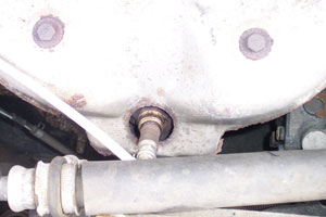
Identifying which O2 sensor has to be replaced also can be confusing. On most 1996 and newer V6 and V8 engines, there are at least two upstream O2 sensors (one for each cylinder bank), and one or two downstream O2 sensors (two if dual converters). Some engines may have as many as six O2 sensors. A fault code for an O2 sensor will indicate the sensor location by sensor number (1, 2, 3 or 4) and by cylinder bank (1 or 2). Sensor No. 1 is usually the one in the exhaust manifold, while sensor No. 2 is usually the downstream O2 sensor behind the converter. Cylinder bank 1 is the same side that also has the number one cylinder in the engine’s firing order. Bank 2 would be the other side.
Replacement O2 sensors have to be the same type as the original with the same number of wires. If one O2 sensor on a high-mileage vehicle has failed, chances are the other O2 sensors may also be nearing the end of their service life and should be replaced at the same time to restore like-new performance.
COOLANT SENSORS
The coolant sensor keeps the PCM informed about the temperature of the coolant inside the engine. This is vital information for the PCM because many control functions vary with temperature. If the coolant sensor is faulty or is reading low, it can throw off the control system possibly causing it to remain in “open loop,” which is a temporary operating mode that should only occur following a cold start. A faulty coolant sensor, therefore, may cause the engine to run richer than normal, resulting in increased fuel consumption and higher emissions.
Input from the coolant sensor also is used to operate the engine’s electric cooling fan. No input or low input from the sensor may allow the engine to overheat because the fan isn’t coming on when it should be.
Coolant sensors can be damaged by overheating, so if the engine has experienced an episode of severe overeating for any reason (coolant leak, bad thermostat, etc.), replacing the coolant sensor is often recommended. A new thermostat also is a good idea.
The coolant sensor’s output can be viewed on a scan tool as a temperature reading. It should match the air inlet temperature (IAT) reading when the engine is cold, and gradually increase as the engine warms up. The sensor’s resistance also can be checked with an ohmmeter and compared to specifications for various temperatures. If the sensor is not reading correctly, it needs to be replaced.
THROTTLE POSITION SENSORS
The throttle position sensor (TPS) is mounted on the throttle body and monitors the position of the throttle opening. The TPS value is displayed on a scan tool as percentage of throttle opening. The PCM uses this information to estimate air flow and engine load. On newer vehicles with electronic throttle control, the sensor’s input also is vital for making sure the throttle is at the correct commanded position.
 Contact-style TPS sensors can develop a worn spot just above the idle position as the miles add up. This, in turn, may create a “flat spot” that results in momentary hesitation or stumble when the driver steps on the gas. This may not set a fault code because the glitch occurs too quickly for the OBD II system to detect.
The sensor’s out put can be checked with a voltmeter, or observed on a scan tool. If there are any drops in the output as the throttle opens, the sensor is bad and needs to be replaced. On some older vehicles, the idle voltage setting of the sensor must be adjusted to a specified voltage.
MAP SENSORS
The Manifold Absolute Pressure (MAP) sensor monitors the pressure differential between intake vacuum and the outside atmosphere. The PCM uses this information to determine how much load is on the engine. If the engine has a “speed-density” fuel injection system that does not use a mass airflow sensor (Chrysler, 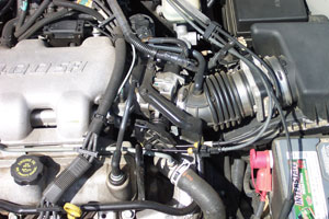 for example), input from the MAP sensor is also used with inputs from the TPS sensor to estimate airflow.
Problems with this sensor can cause hesitation, fuel mixture and spark timing problems. The sensor’s output can be read on a scan tool, or checked by reading its frequency or voltage output on a DVOM. If the sensor is reading out of range, check the sensor’s connection to the intake manifold for a possible vacuum leak. If there’s no leak, the sensor needs to be replaced.
MASS AIRFLOW SENSORS
The Mass AirFlow (MAF) sensor is usually located between the air filter housing and the throttle. The MAF sensor uses a heated wire or filament to measure airflow into the engine. This is vital information for controlling the fuel mixture. The most common problem here is contamination of the sensor element with dirt or fuel varnish. A dirty MAF sensor will typically report less airflow than is actually occurring. This can cause a lean fuel condition, hesitation and reduced performance. The sensor’s output can be observed on a scan tool, and should go up as the throttle opens and airflow increases. A sluggish or unresponsive MAF sensor can often be restored to normal operation by cleaning the sensor element with aerosol electronics cleaner (do not use any other type of cleaning chemical as this may damage the sensor!). If cleaning doesn’t do the trick, the sensor needs to be replaced.
CRANKSHAFT & CAMSHAFT POSITION SENSORS
The Crankshaft Position (CKP) sensor keeps the PCM informed about the relative position and rotational speed of the crankshaft. Many engines also have a Camshaft Position (CMP) sensor that helps the computer figure out the correct firing order of the engine. A failure of either sensor may prevent the engine from starting or running.
Two types of sensors are commonly used for these applications: magnetic sensors or Hall effect sensors. Magnetic sensors have a wire coil wrapped around a magnetic core. When the tip of the sensor passes over a notch on a ring attached to the crank, it changes the magnetic field and produces a small current. With Hall effect sensors, a reference voltage is supplied to the sensor by the PCM to detect notches in the crank wheel.
Crank sensors may be mounted on the front of the engine and read notches in the crank pulley, or mounted in the block to read a notched ring on the crank itself. The cam sensor(s) if used, are usually mounted in the cylinder head(s) and read a ring on the camshaft(s).
Loss of a signal or an erratic signal will usually set a fault code. The resistance of magnetic sensors can be measured with an ohmmeter. If out of range, the sensor needs to be replaced. The sensor ring also needs to be inspected for damaged, missing or cracked teeth as any of these conditions can cause erratic sensor readings.
Note: On many GM applications, a special relearn procedure using a scan tool must be performed after replacing a bad crank sensor. If this is not done, the engine may not start or run normally.
SPEED SENSORS
Most late model vehicles have several magnetic speed sensors. The Vehicle Speed Sensor (VSS) is usually located on the transmission output shaft and provides a signal that is proportional to vehicle speed. The transmission also has one or two additional internal sensors for monitoring the relative speeds of the main input and output shafts. On vehicles equipped with antilock brakes, there are usually Wheel Speed Sensors (WSS) to monitor each of the wheels.
Faults in speed sensor circuits usually tend to be wiring related rather than outright sensor failures. However, magnetic sensors can become fouled with iron particles that stick to the tip of the sensor (brake dust from semimetallic brake pads that stick to a wheel speed sensor, or iron particles inside a transmission or differential that stick to a speed sensor). Sensor inputs can be viewed on a scan tool, or checked by measuring their resistance with an ohmmeter. If the wiring is okay but the sensor is reading out of range, the sensor needs to be replaced.
Note: On vehicles where the wheel speed sensor is an integral part of the hub and wheel bearing assembly, the entire hub must be replaced if the sensor is bad. The ABS system will not operate unless it has good signals from all of its sensors.
TEMPERATURE SENSORS
The engine management system uses an Inlet Air Temperature (IAT) sensor to monitor air temperature because changes in air temperature affect air density, which in turn affects the fuel mixture. A sensor that is not reading accurately can upset the fuel mixture causing an increase in emissions and fuel consumption as well as drivability issues. The sensor’s output can be shown on a scan tool, or measured with an ohmmeter. If out of range, the sensor needs to be replaced.
The heating ventilation and air conditioning (HVAC) system also uses air temperature sensors to monitor air temperature within the passenger compartment. A bad sensor won’t turn on the Check Engine light because it does not affect emissions, but it can cause problems with regulating heating and cooling if it is out of range.
Note: Many vehicles also have a dash-mounted sun sensor that detects bright sunlight so the HVAC system can compensate for solar heating.
TIRE PRESSURE SENSORS
All 2006 and newer passenger cars and light trucks are equipped with tire pressure monitor systems (TPMS) to keep an eye on tire pressures. The system will alert the driver if pressure drops 25 percent or more below the recommended inflation pressure. Most TPMS sensors are mounted on the end of the valve stem inside the wheel, though some older systems use a large TPMS sensor attached with a steel band to the drop center inside the wheel.
TPMS sensors have an internal battery with a limited service life that may range from five to seven years. Once the battery goes dead, the sensor needs to be replaced. Replacement is usually recommended when the tires are replaced. TPMS sensors also can be fouled by some types of tire sealer products.
A TPMS sensor’s ability to generate a good signal can be checked with a special TPMS tester that energizes the sensor and listens for a radio signal back from the sensor. If a sensor has failed or is not reading accurately, it needs to be replaced. “Universal” aftermarket TPMS sensors are available for a wide variety of applications. Following replacement, a special relearn procedure must be performed so the TPMS system can relearn the position of each sensor correctly.

