ABS System Overview: A closer look at this important safety system
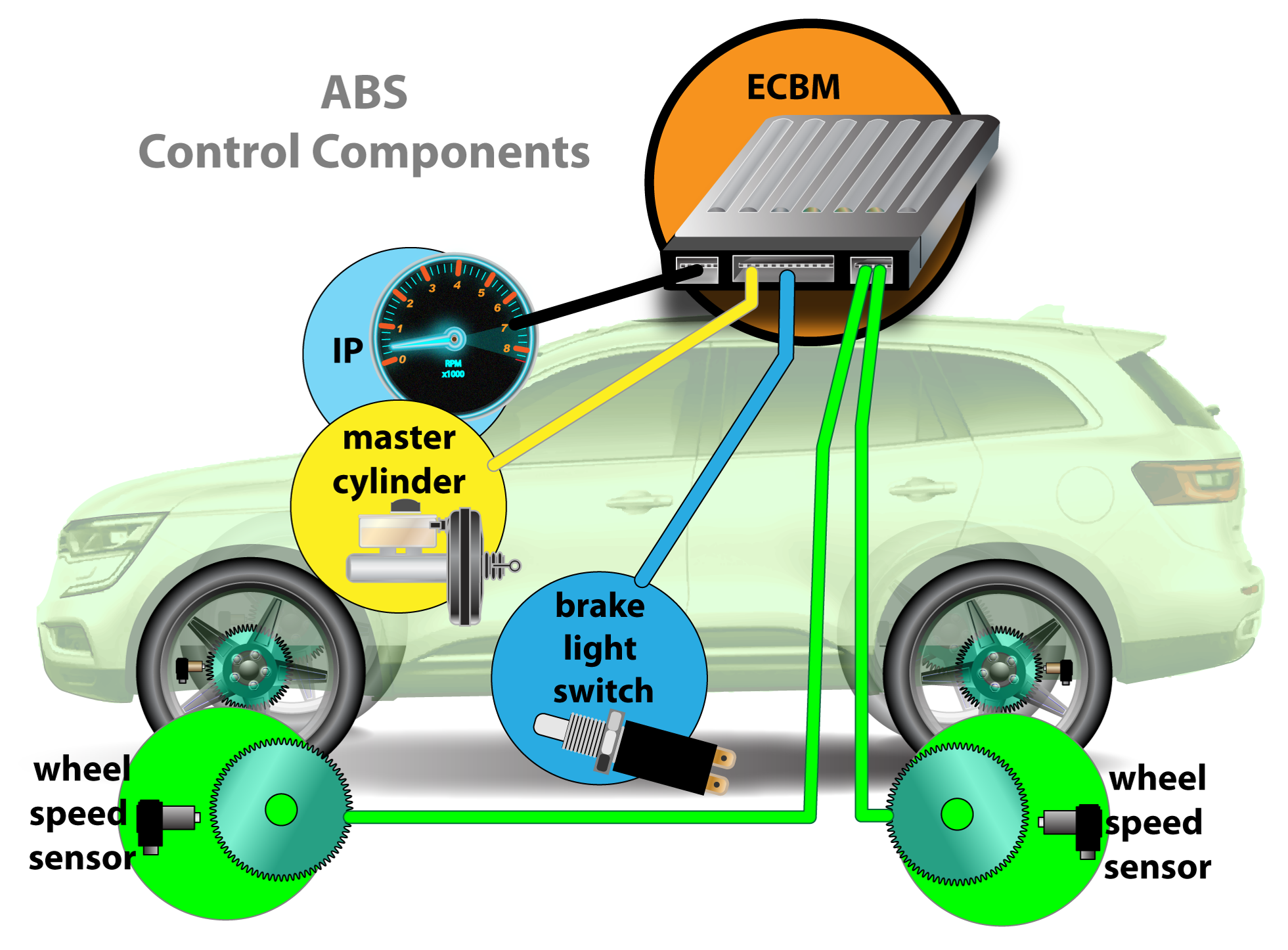
In order to maintain vehicle control, the Anti-lock Braking System (ABS) is concerned with monitoring and controlling wheel slip. The major components to every ABS system are: wheel speed sensors, brake switch, brake master cylinder, EBCM, and hydraulic assembly containing the pump motor, accumulator, valves, and solenoids.
The Heart of the ABS System – Wheel Speed Sensors
There are two categories of wheel speed sensors; passive and active. VR or variable reluctance sensors are a magnet within a coil of wire. Signals are generated by rotating a metal reluctor past the sensor. Active wheel speed sensors are magneto-resistive that produce a digital signal, and the amplitude change is typically about half a volt.
Wheel speed sensors and ABS status can be monitored on the scan tool. This is a great starting point for any ABS issue after codes have been checked.
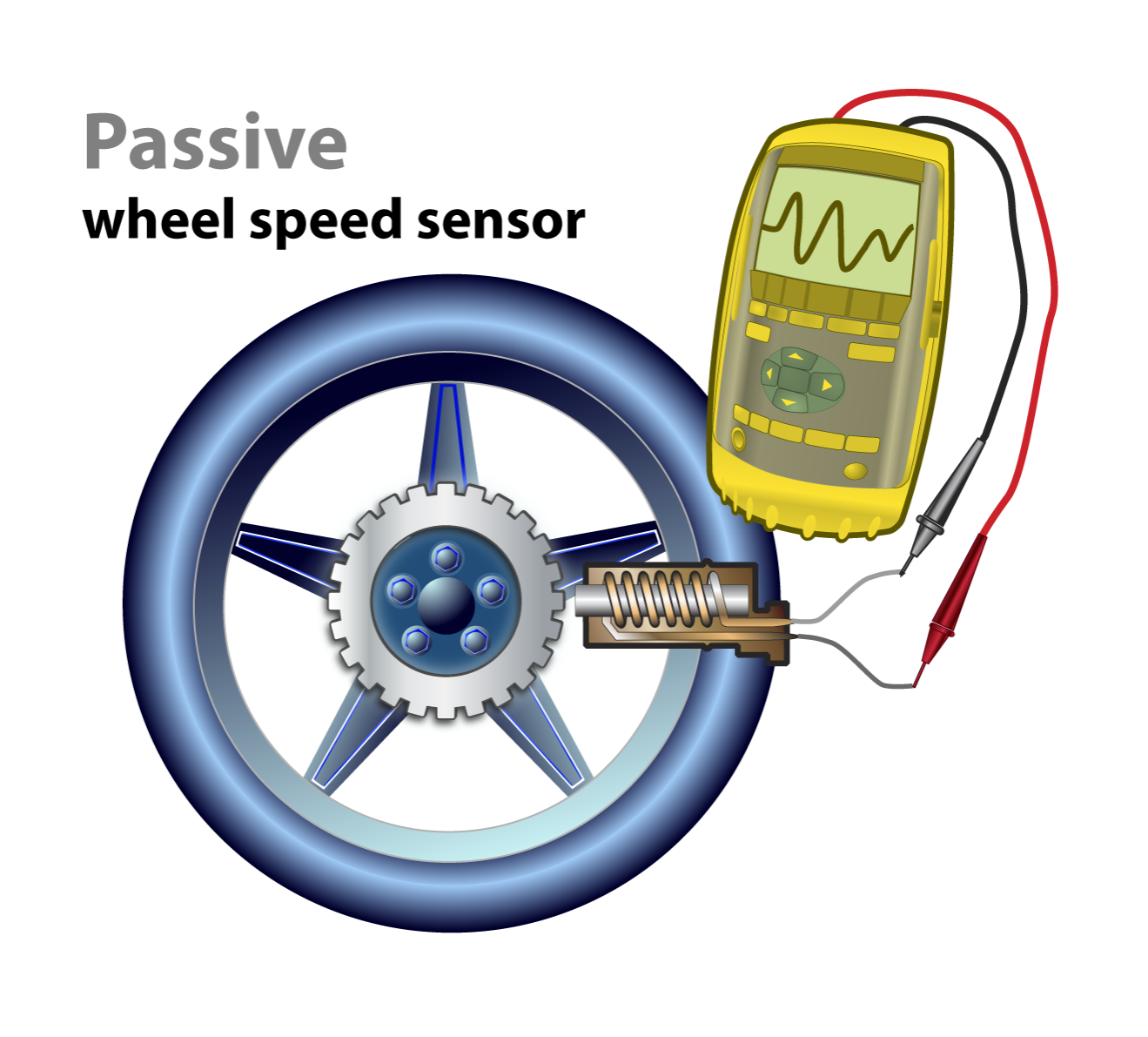
The first and most widely used are called passive wheel speed sensors. These are VR or variable reluctance sensors and are essentially just a magnet within a coil of wire. Signals are generated by rotating a metal reluctor past the sensor. As the cogs approach the sensor, the magnetic field expands and then when the cog moves away from the sensor, the magnetic field collapses. The expanding and contracting magnetic field induces an AC voltage into the sensor, which is then recognized by the EBCM as a speed signal based on the frequency of the changes.
VRS sensors do not require power to operate. These sensors generate AC voltage. Signal strength is dependent upon speed and they are not effective at low speeds. This is why VR sensors are not used in stability control systems. Technicians can test the resistance of the sensor with their Ohm meter. Expected resistance will be somewhere between 1,000-2,500 ohms. It is important to check the vehicle’s service manual to confirm these specs, though often the resistance spec will be found in a testing procedure instead of specs. Air gap between the sensor and tone ring is critical.
To test the resistance of a VRS, unplug the sensor and probe across the two wires. There could still be issues with the sensor, tone ring, and wiring. This test will prove that a sensor is bad if a high resistance is measured but does not prove the sensor is good.
Responding to the need for better onboard diagnostics and the ability to detect even lower wheel speeds, engineers created the active wheel speed sensor. There are two basic types we will arbitrarily refer to as type 1 and type 2. Within both types is a magneto-resistive circuit. While technically not accurate, for our purposes we will simplify the sensor’s operation by considering it essentially a variable resistor with two states; high and low resistance.
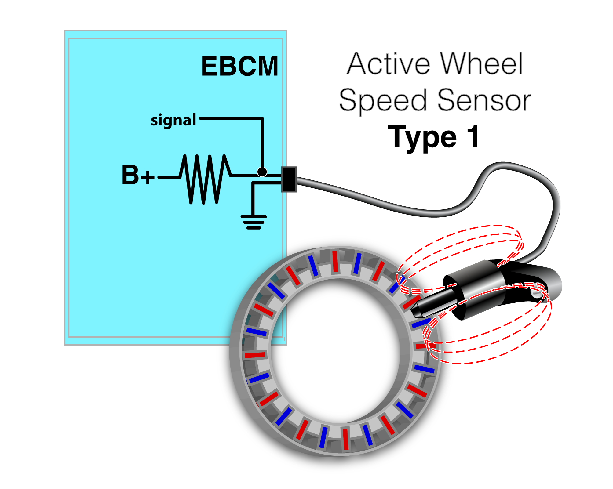
The type 1 sensor uses a hub that has magnets embedded into it with alternating polarity. As the hub moves past the sensor, the sensor’s resistance changes states. The EBCM supplies the sensor with B+ through an internal resistor and ground which creates a voltage divider circuit.

The type 2 active wheel speed sensor incorporates a magnet inside of the sensor itself. Instead of a hub with an embedded set of magnets, the hub has a simple reluctor. As the reluctor passes by the wheel speed sensor, it will act as a variable resistor with two states. The EBCM supplies the sensor with B+ through an internal resistor and ground, which creates a voltage divider circuit. When a magnetic field is applied or increased within the sensor due to the rotating hub, the effective resistance of the sensor changes. There are only two possible state changes, and this creates an output of two different voltages.
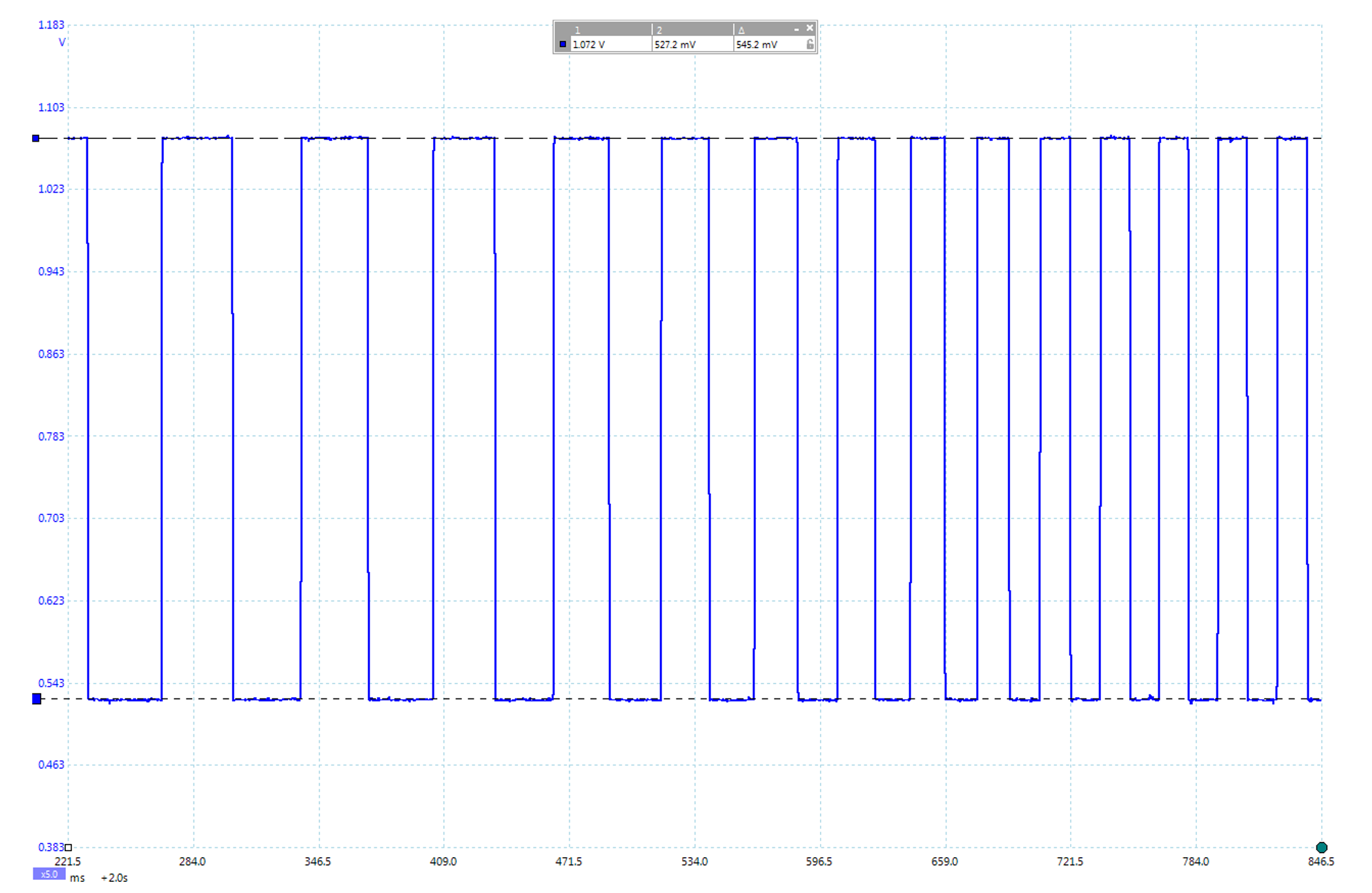
All active wheel speed sensors produce a digital signal, and typically the amplitude change is only about half of a volt. If a technician needs to test an active wheel speed sensor, the simplest test is to ensure that the resistance is proper. These are polarity sensitive so it is important that the meter is hooked up properly. If the resistance is in spec, the next test should be to measure the output. While this can be done with a meter, the most accurate method is to monitor it using a lab scope.
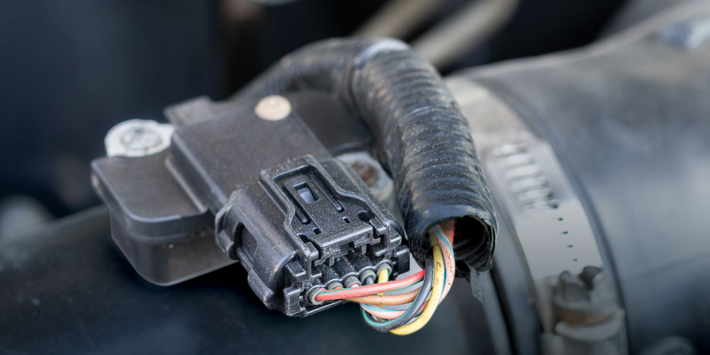
Regardless of sensor type, if a wheel speed sensor is suspected to be bad, it is important to also test the wiring to check proper operation. The wires are subject to significant movement as the chassis and suspension moves, and there may be intermittent faults due to wiring defects. Many manufacturer trouble trees will have the technician do an open circuit check on the harness. This test can be misleading and cause misdiagnosis. The wires are low current and low voltage but must be in working condition. The wires must be load tested to check proper operation. One method is to disconnect the sensor and module; applying power at one end and a test light at the other end – this will load test the wiring. This method is something any tech can perform.
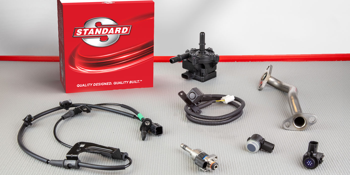
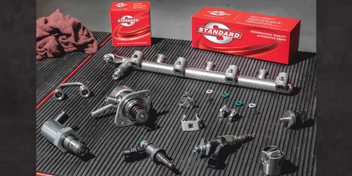
Premium Replacements for an Important Safety Category
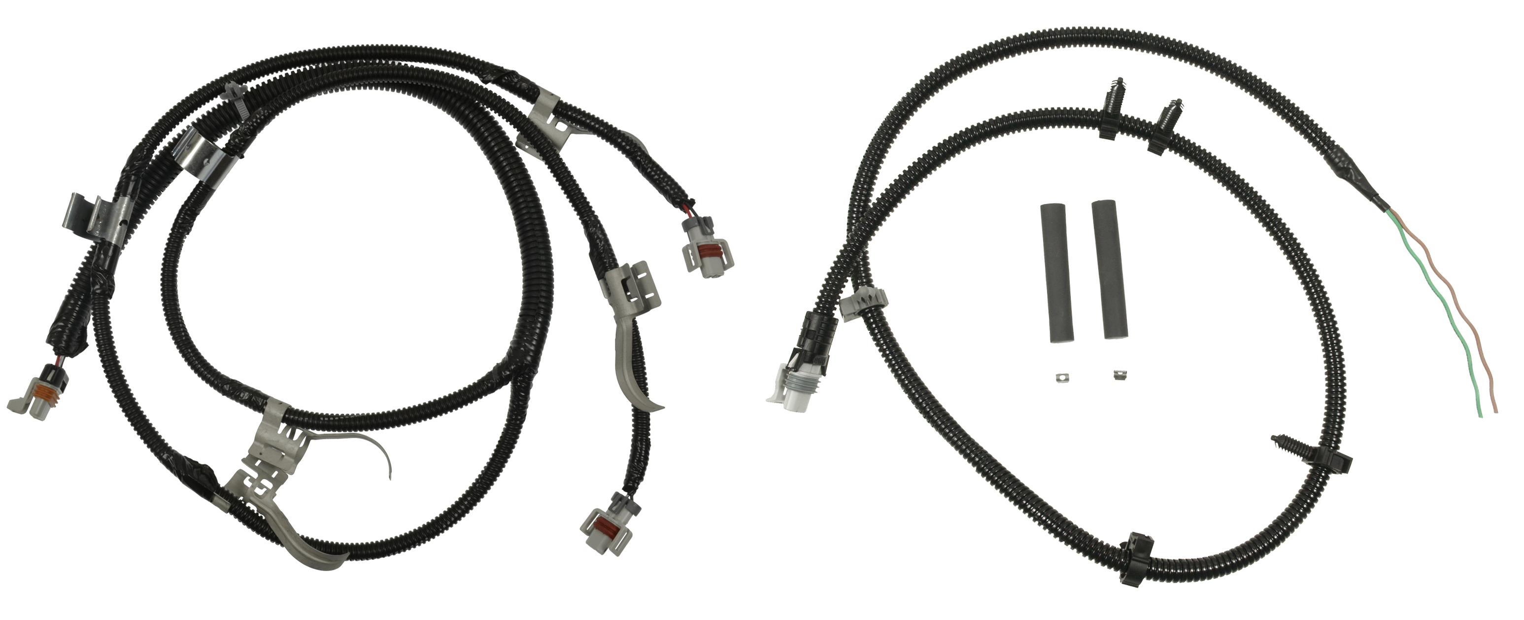
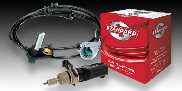
Along with industry leading coverage, Standard® delivers the quality professional technicians depend on. In addition to premium sensors Standard® offers complementary connectors and harnesses. When you need to replace an ABS sensor or just a connector or harness, look to Standard® for your next ABS repair.
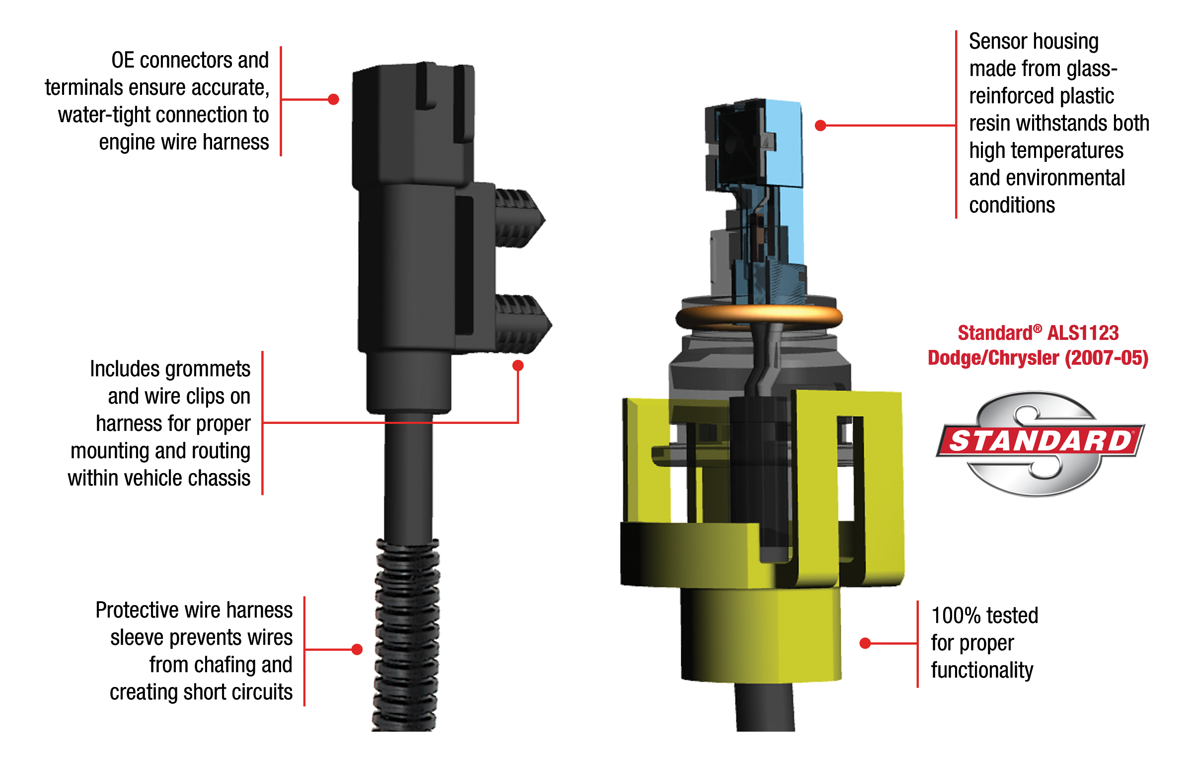
Standard® offers more than 2,500 ABS Speed Sensors for import and domestic applications for 96% coverage. Standard® ABS speed sensors are designed to provide consistent performance, matching the OE for form, fit, and precision function. Features such as superior magnetic circuit materials are engineered into Standard® sensors to deliver higher voltage output preventing ABS system failure. Superior design and extensive laboratory plus real-life testing is why Standard® ABS sensors perform equal to or better than the original. To learn more visit StandardABSsensor.com and check out our ABS Sensor Playlist on YouTube!
This article was sponsored by Standard®