 MAJOR COMPONENTS & FUNCTIONS
* Battery — Stores electrical power for starting the engine and powering electrical accessories. Most automotive batteries are lead-acid 12 volts with six “cells” of stacked positive and negative lead plates. The plates are separated by insulators and immersed in a water/sulfuric acid mixture called the “electrolyte.” Maintenance-free design eliminates need to add make-up water. Some batteries use an “absorbent glass mat” construction with the acid in a spill-proof “gel” form between the plates.
Batteries come in various “group” sizes with different heights, widths, lengths and post configurations (top posts or side posts). Batteries also have different power ratings (“Cold Cranking Amps” or CCAs) which can range from 450 to 1,000 CCA. A replacement battery must have same or higher CCA rating as the original, and be a compatible group size to fit the vehicle’s battery tray and cable connections.
Average battery life is about four to five years, and is usually shorter in hot climates. An old battery may not accept or hold a charge. Battery failure can be caused by heat, vibration, undercharging or overcharging.
Batteries have a limited shelf-life, so ones with the oldest date code should be sold first.
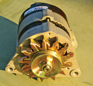
 * Alternator & Voltage Regulator — The alternator generates voltage to maintain battery charge, and to power the vehicle’s electrical and electronic components. The alternator is belt-driven by the engine, and produces an alternating current (AC) that is converted into 12 volts of direct current (DC) by diodes (rectifier) in the back of the unit. The alternator’s charging output is controlled by a voltage regulator (which is usually mounted in or on the unit, but may be mounted elsewhere in older vehicles), or by the powertrain control module (PCM). Alternator output is rated by how many amps it can produce, which typically ranges from 60 up to 180 or more depending on the application.
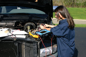
Low charging voltage can occur if one or more diodes in the alternator fail, if the alternator brushes are worn, if there are poor wiring connections inside or outside the alternator, or if the voltage regulator fails. This will allow the battery to run down very quickly, and eventually the vehicle will stop running. The alternator’s charging output can be tested with a volt meter, ammeter or an alternator bench tester. Replacement alternators must have the same or higher amp rating as the original.
* Starter — An electric motor used to crank the engine so it will start. Power is routed to the starter motor through a relay or solenoid (which may be mounted on the starter or elsewhere). When the motor spins, the gear drive engages the flywheel to crank the engine. As soon as the engine starts, the gear drive retracts. Some starters have “reduction gears” to increase their torque output. Some also have “permanent magnets” instead of field coils to reduce size and weight. Slow cranking may be symptom of bad starter, low battery or poor battery cable connections. No crank may indicate failed starter, solenoid or bad ignition switch, or an anti-theft issue. Starter motor can be checked with an ammeter to measure amps used, or bench tested to check cranking rpm and current draw. Starter failure can be caused by prolonged cranking if engine does not start.
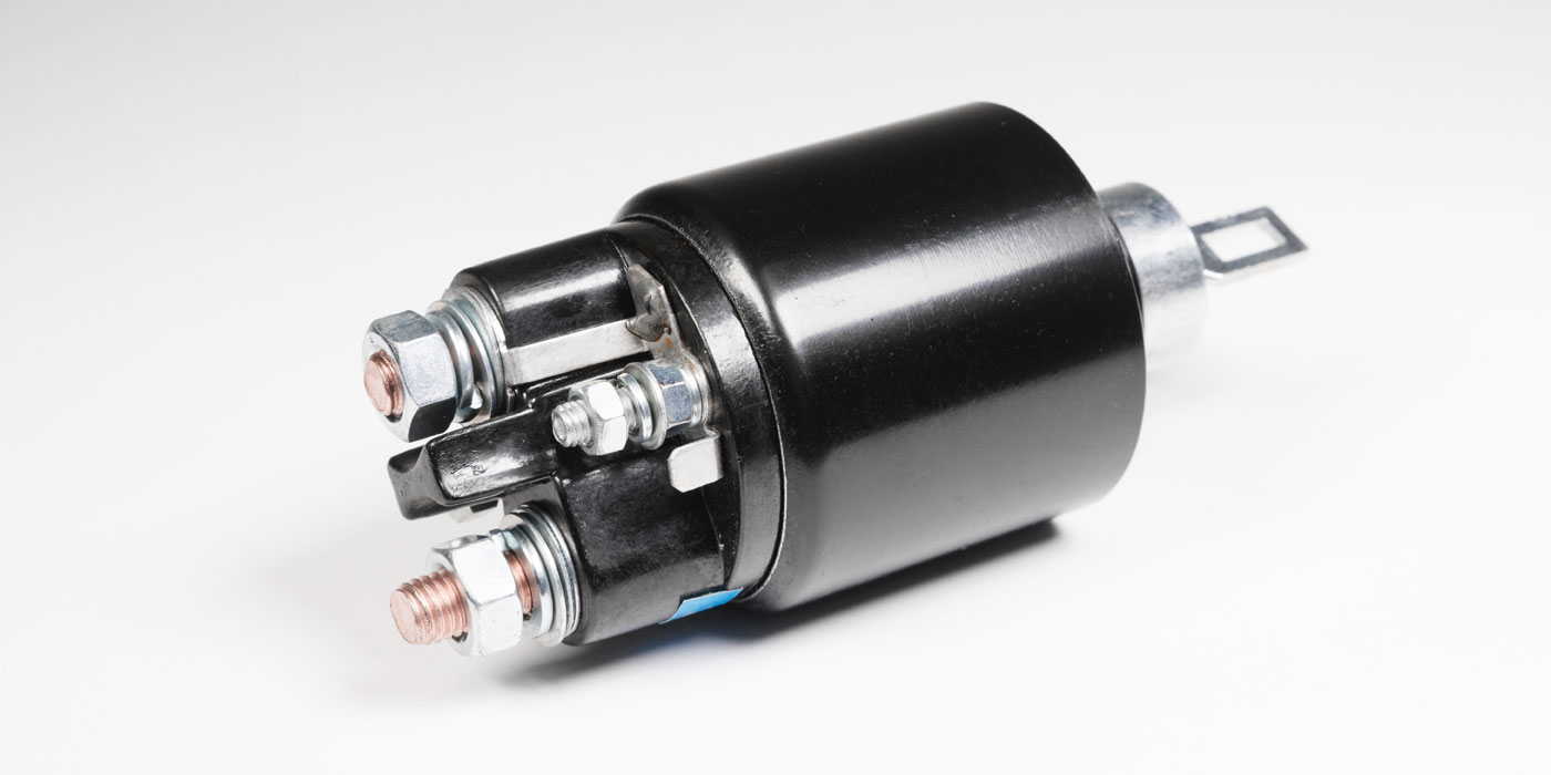
* Starter Solenoid or Relay — Devices used in the starter circuit to route power from the battery to the starter motor. The solenoid may be mounted on the starter itself, or elsewhere in the engine compartment. Poor wiring connections at the solenoid or relay can prevent the starter from cranking.
RELATED ITEMS
* Battery Cables — Old cables with damaged or badly corroded terminals should be replaced. The negative (-) cable connects to “ground” (engine or chassis), and the positive (+) cable connects to power distribution center, solenoid or starter. Positive cables may be color-coded red, negative cables color coded black.
* Ground Straps — Connects engine to body or chassis. May cause starting, charging and electrical problems if missing, loose or broken.
* Fuses — Protect electrical circuits from damaging overloads. Replacement fuse must have same amp rating as original. Located in fuse box under instrument panel, power distribution center in engine compartment, and some in-line wiring connectors.
* Relays — Electrical switching devices that route power to various circuits and components. Located in power distributor center in engine compartment, fusebox under dash or elsewhere.
* Wiring terminals and splices — Used to repair and fabricate wiring connections.
* Special Tools — Voltmeter, digital multimeter (DVOM), 12-volt test light, continuity testers, wire cutting, stripping and crimping tools.
INSTALLING ELECTRICAL SYSTEM PARTS
Batteries are “dry charged” at the factory, but should be fully charged prior to installation to minimize overloading the charging system.
Alternators have a high return rate because charging problems are often misdiagnosed. The fault often turns out to be something other than the alternator. Bench testing the old alternator can reduce unnecessary comebacks. Charging output on the vehicle should be tested after installation to confirm the alternator is charging the battery.
The battery ground cable should usually be disconnected when doing electrical repairs, but on late model vehicles this may cause the PCM and other electronic modules to forget learned settings. This, in return, may prevent some systems from functioning normally until they undergo a special “relearn” procedure (which may require using a factory scan tool in some cases). Using a battery backup memory saver can prevent the loss of this information, and is highly recommended when disconnecting or replacing a battery on a late model vehicle.