At the same time the auto industry was dipping its toes into technology, I was your typical high school adolescent who only cared about the cars I could afford – which at that time was nothing newer than mid-‘70s iron.
The only language I knew was that of carburetors, camshafts, headers and hot rods, and growing up in a college town, I thought lambda was a fraternity. In a few short years when I entered both the auto repair industry and technical college, I found out I had a lot to learn.
All of a sudden, I had to learn technology, which required first off to learn the terminology. Oxygen (O2) sensors were new to me, and then throwing in the term “lambda” made it all seem complicated. I eventually learned that it really wasn’t, but I also learned not to get wrapped up in all the overly technical jargon.
From a technician standpoint, I needed to understand how things worked – not re-engineer them – so here’s what I taught myself to know about O2 sensors, and I promise I won’t use the word “lambda” … at least for a while.
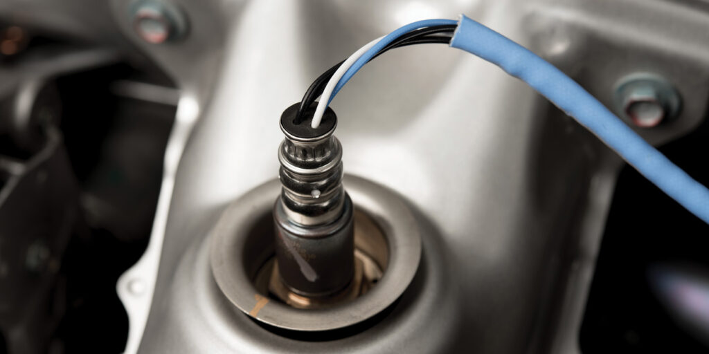
O2 sensors have a simple function. They generate voltage, and their job in an automotive context is to provide a varying output voltage in response to the amount of oxygen in the exhaust. Determining the amount of oxygen in the exhaust is what allows modern engine-management systems to calculate the efficiency of the combustion process and adjust the fuel delivery to maintain the correct air/fuel ratio.
So, how do they do this? The principal is an electrochemical reaction that takes place, the catalyst for which is the difference between the amount of oxygen in the air we breathe compared to the amount of oxygen in the exhaust. In order to get the “outside” sample of air, some O2 sensors have provisions that allow air into the body of the sensor; others have a sealed sample inside.
One of the important factors in the operation of an O2 sensor is heat. The bottom line is they can’t produce an accurate signal until they’re warmed up. Until an O2 sensor is warmed up, the computer will run the engine in a mode called open loop. All this means is that it’s running on pre-programmed parameters, but it also means it’s not running efficiently since it’s not yet utilizing the critical data from the O2 sensor that it needs to adjust the air/fuel ratio.
When the O2 sensor warms up, the engine computer will switch to closed-loop operation, meaning it’s now adjusting the air/fuel ratio based on the input it receives from the sensor(s). Since this is so important for emissions, the quicker the O2 sensor warms up, the better. Location or placement in the exhaust has an effect on how quickly they warm up, but the two biggest factors are the addition of built-in heaters and higher idle rpm when the engine is cold.
High rpm also is important to warm up the catalytic converter, since they don’t work efficiently until warm either. But enough of that. Let’s move on.
AFR Sensors
So, you have an idea of what an O2 sensor does and when it does it. It’s time to throw a wrench in the works. There’s another sensor called an air/fuel ratio (AFR) sensor. An AFR sensor also is called (or nicknamed) a wideband O2 sensor. What they ultimately do is the same thing, and up to this point in the article, feel free to switch the term O2 with AFR.
They also look basically the same and mount the same. We often call them all O2 sensors, and nobody gets really hung up on it, because they’re close enough. AFR sensors, however, have different operating parameters because they have a wider range and are able to provide more precise information to the vehicle computer. They simply are a more accurate version of an O2 sensor.
The fact that they operate differently is obviously critical for diagnostics, but it’s also just as important from the standpoint of replacement. The only acceptable replacement is a sensor that is specified for the exact vehicle in the exact location on the vehicle. An O2 sensor won’t work in place of an AFR sensor, or vice-versa. Some vehicles also have both types of sensors installed, making it more important to confirm which sensor is being replaced.
Most modern vehicles have two sensors on each bank of the engine. An inline engine only has one bank (with the exception of a couple strange anomalies out there that you may run across), and any V-configured engine has two banks. When you sell an O2 or AFR sensor, you’ll need to know the location referenced as Bank 1 Sensor 1, Bank 1 Sensor 2, Bank 2 Sensor 1 and so on.
Real-World Operation
Let’s touch briefly on operation. Ideally, we would like to make an engine run at the perfect air/fuel ratio (referred to as stoichiometric ratio) at all times. In the real world, that’s not possible due to constantly changing parameters of engine operation, so the best we can do is allow the engine computer to make constant adjustments.
An O2 sensor (not an AFR sensor) is only able to send basic voltage signals of rich or lean. When it sends either signal, the control unit reacts and adjusts the fuel mixture. So, for example, if it sees a rich signal, it will continue to lean out the mixture until it sees a lean signal. As soon as it sees a lean signal, it then will begin to enrich the mixture until it sees a rich signal. This all happens really fast of course, and on an oscilloscope, normal O2 operation will look like a consistent waveform ranging from about .2 volts (a lean signal) to approximately .8 volts (a rich signal). As long as the average between the high and low readings is about .45 volts (450 millivolts), we know that the sensor is operating correctly, and the control unit is able to maintain the proper fuel mixture.
An AFR sensor operates in conjunction with the control unit through current flow. The current flow changes direction for rich or lean, and when the mixture is at the stoichiometric ratio, current flow stops. The AFR sensor also increases or decreases the current flow (in either direction) in direct proportion to the changing rich or lean condition. This provides much more information to the control unit, allowing it to better predict and control fuel mixture.
On an oscilloscope, normal operation is similar to that of an O2 sensor, but the voltage can vary in a range from 0 up to 5 volts. Lower voltage indicates a rich signal, whereas higher voltage indicates a
lean signal.
I may have bridged the gap of too much technical information, but it’s all more knowledge you can share with your customer and use to your advantage when explaining the importance of a quality sensor. Undoubtedly, you’re also going to be asked two things. One, how to tell if a sensor is bad; and two, tips about replacement.
Diagnosis
Diagnosing a sensor can be difficult when it comes down to the level of using an oscilloscope, primarily because it takes a lot of experience to get familiar with reading the waveforms. So, here’s a good way to approach it when your customer asks.
Generally speaking, a customer buying an O2 sensor is almost always trying to “fix” the “Check Engine” light because of an O2-sensor code. If the stored code is related to the sensor heater, diagnosis should be easy. The control unit provides power and ground to the heater, and wiring problems are very common. Check for power and ground at the sensor connector wires. If you have it, the sensor heater is bad and the sensor needs replaced. If you don’t have it, there’s a wiring issue.
If the code is related to sensor operation, it could be a bad sensor, bad wiring or another problem such as a vacuum leak or leaking injector. You have to be careful about misdiagnosis, so it’s fair to recommend your customer have the problem professionally diagnosed. However, it’s a fact that O2 and AFR sensors will wear out with age.
Since we know it’s a chemical reaction that takes place to make them work, think of it like a traditional car battery. A chemical reaction takes place to generate electricity in a battery, and over time the ability for that chemical reaction to take place diminishes. The same is true with an O2 or AFR sensor. They simply wear out. Don’t be afraid to recommend them based on age.
O2 and AFR sensors also are very sensitive electronic devices, and they can be damaged by coolant, engine oil, incorrect fuel or silicone and sealants that are not safe for use with them, so beware of these other outside possibilities that can
ruin them.
Installation Tips
When asked about installation, here are some tips. All sensors, O2 or AFR, are 22 millimeters. There are many different O2-sensor sockets, which are designed to allow you to remove the sensor without damaging the wiring harness. This is really only important if you are removing a sensor for access to another repair.
If the sensor is bad, there’s no need to worry about the wires. Cut them off at the sensor and use a 22-millimeter wrench or socket. The most common thing that happens during replacement is that you break the sensor loose, get about a quarter-turn on it and it locks up. You have to be patient at this point and allow penetrating oil time to work its way in, then slowly work the sensor back and forth until you can remove it.
Thread damage is common, but almost always repairable using a thread chaser or tap. Most new sensors come with a little anti-seize on the threads, but if not, use a high-temp anti-seize for installation.
The ‘L’ Word
I know I promised I wouldn’t use the “L” word, but just for the record, lambda is a numerical representation of stoichiometric ratio, which itself is a reference to air/fuel ratio. Most of us know 14.7:1 – the stoichiometric ratio for gasoline, which is necessary for complete combustion, or for all fuel to burn with no excess air left over. What’s tricky is that the stoichiometric ratio is different for alternative fuels.
In other words, all fuels don’t require the 14.7:1 ratio for correct combustion. E85, for example, has a stoichiometric ratio of 9.77:1 for correct combustion. The lambda value for the ideal stoichiometric ratio, regardless of fuel type, is 1.00. Basically, it’s just a different scale, like using the metric system vs. fractional. Utilizing the lambda value has become more popular in recent years, primarily due to the interest in aftermarket vehicle tuning. Many tuners utilize lambda simply for consistency, but you have to be careful. Some control units use lambda numbers, some use stoichiometric, so when you’re at that level, you just need to know what you’re dealing with.