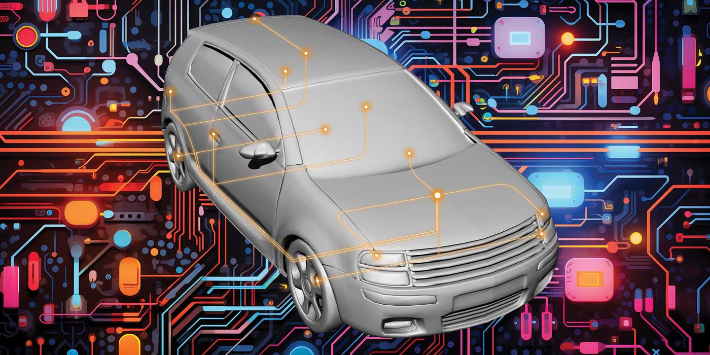
“CAN” stands for Controller Area Network. It’s the basic operating system for the wiring and electronics in late model vehicles. The CAN system ties together all the major control modules in the vehicle and allows them to talk to each other, share data and interact in ways that were not possible before CAN arrived on the scene.
Before CAN, every system on a vehicle was essentially a separate entity and pretty much did its own thing with little or no interaction or input from other systems. With CAN, that’s no longer the case. CAN links all the different systems and modules together into an integrated network. This allows the powertrain control module, body control module, antilock brake module, airbag module, climate control module, lighting control modules, electronic instrument cluster, keyless entry system, tire pressure monitoring system and all the other modules to work together in ways that were impossible before CAN.
For example, the stability control system can interact with the PCM and transmission to reduce engine power if a wheel is spinning or losing its grip. The climate control system can ask the PCM to increase idle speed if the A/C compressor is working hard to cool down the interior. The keyless entry system can signal the lighting modules to turn on the interior and/or exterior lights when the vehicle owner approaches the vehicle with his key fob. The airbag module can signal the PCM to shut off the engine in event of an accident. On vehicles equipped with “active” lighting, the aiming of the headlights can change right or left depending on inputs from the steering wheel sensor. Such applications will continue to increase in both complexity and sophistication as more and more safety and convenience features are added to new vehicles.
The downside of all of this, unfortunately, is that a problem in one system can sometimes affect the operation of what seems to be a totally unrelated system. This can happen as a result of bad data being shared, scrambled communications between modules, or shorts or opens in shared wiring circuits.
GROWING COMPLEXITY
The first CAN-equipped cars appeared back in the late 1990s, with more being added with each new model year throughout this decade. In 2008, CAN became standard on all cars and light trucks.
The communication protocols for CAN systems conform to international standards (ISO 15765) and are divided into three groups:
•CAN A is for low-speed communications with a baud rate of up to 10 kilobytes per second (Kbps). This is used for low-priority devices such as power windows, seats, door locks, lights, etc.
•CAN B is for medium-speed communications of 33 to 250 Kbps. This is used by systems that have to send and receive large amounts of data such as the electronic instrument cluster, the climate control system, certain emissions functions, the automatic transmission and the keyless entry system.
•CAN C is for high-speed communications from 250 Kbps up to 1,000 Kbps (1 meg). This is used by the powertrain control module, ABS/traction control/stability systems, and supplemental restraint system (air bags).
HOW IT WORKS
In a traditional electrical system (before CAN), each electrical component or system had its own individual wiring circuit. There was a separate wiring circuit for the starter, charging system, ignition system, fuel pump, fuel injectors, engine control module, sensors, exterior lights, interior lights, heater and air conditioning system, radio, horn, power windows, power seats, power door locks and everything else. This added up to hundreds of separate circuits and literally miles of wire snaking throughout the vehicle.
With CAN, the wiring is “multiplexed.” Multiplexing means sharing circuits to reduce the number of individual wires needed to operate the vehicle’s electrical and electronic systems. Multiplexing typically reduces the number of wiring circuits up to 40 percent or more to reduce the weight, bulk and cost of the wiring harness.
Multiplex wiring uses digital signals and coded messages to switch various functions on and off. It also allows components that are connected to the same control circuit to share information and talk to each other.
In a CAN wiring system, one wiring circuit is used for command signals, feedback and data transmission. This is called the “data bus.” Separate circuits are used for power and ground, the same as a conventional wiring system. The command signals, and other information that is transmitted over the data bus are sent as coded digital messages by a “gatekeeper” module, which is usually the body control module.
The gatekeeper module controls the flow of traffic in the CAN system so the messages don’t collide or become garbled. The gatekeeper module also links the components that are multiplexed together to other modules or wiring circuits in the vehicle. The gatekeeper module also may tell certain modules to go into “sleep” mode when the ignition is turned off and then ping them to wake them up when they’re needed again. The gatekeeper is also the module that keeps track of all the addresses of each node in the multiplex wiring system (which may require a special relearn procedure or reprogramming with a scan tool if power is lost or a module is replaced).
DIGITAL TALK
Each message in a CAN network is coded in binary language with “1s” and “0s” that represent numbers, values or commands. The “1s” and “0s” are called “bits” and these add up to make chains of 8-digit “bytes.” It’s the same lingo that computers use to process information and communicate.
The speed of transmission is known as the “baud rate,” and the higher the baud rate, the faster the system can communicate and process information.
To make this work, mini-control modules are needed at every “node” in a multiplexed CAN wiring system where components are connected to the data bus. Each node is assigned its own unique numeric address so the gatekeeper module and other modules attached to the system can identify it. The address system assures messages that are sent over the common data bus are received at the correct destinations, and that data sent from any node in the system can also be identified as to its source.
The address for each module is like a house number on a street or a telephone numbers in a directory. It’s a three-digit number. For example, on a 2007 GM Cadillac XLR, the engine control module address is 017, the transmission control module is 024, the body control module is 064, and the electronic brake control module is 040.
CAN DIAGNOSTICS
Late model CAN wiring systems require a CAN-compliant scan tool for diagnostics. A CAN-compliant scan tool has the circuitry that can read the various data baud rates. Older scan tools won’t work because they were not designed to read CAN data. Consequently, upgrading to a CAN-compliant scan tool is necessary to work on newer vehicles.
If a fault occurs in the multiplex wiring in a CAN vehicle, it can set a “U” communications fault code and turn on the Malfunction Indicator Lamp (MIL). The number that follows the U-code will correspond to the type of fault. When the first digit in a U-code is a 0, it is a generic OBD II code. If the first digit is a 1, the code is a manufacturer specific code.
Modules typically send out a “node alive” message every two seconds. This is sort of a wake-up call that lets their neighbors know they are still alive and functioning. This is called “state of health” monitoring. If no node alive message is received from a particular module for 5 to 10 seconds, a DTC U1xxx communications error code is set where xxx corresponds to the three-digit identification code for the module that went silent. So if the malfunction indicator lamp (MIL) is on and your scan tool displays a DTC U1040, it would tell you there is a communication fault with the electronic brake control module.
The important point to keep in mind with respect to CAN module codes is that the code does not mean the module has failed and needs to be replaced. The code only tells you the module is not communicating with the CAN system. It might be a bad module, or it might just be a bad wiring connection.
U-codes can be set by loose or corroded wiring connectors, by open or shorted wires, or by module faults. Diagnosis requires looking up the vehicle manufacturer’s trouble code chart for the U-code, then following the step-by-step procedures to isolate the problem.
No modules should be replaced until the power, ground and network wiring connections to that module have all been checked out. Aerosol electronics cleaner can be used to clean module wiring connectors and will often clear up intermittent problems that set communication error codes.
Advanced diagnostics on CAN systems also requires a professional level scan tool. A basic scan tool or code reader is okay for pulling codes, but it lacks the bidirectional capabilities and test features of more expensive professional scan tools. One of the things you can do with a professional scan tool is “ping” a module to see how it responds. The tool sends a wake up signal to the module address to see if anybody is home. If there’s no answer or the response makes no sense, you know the module is bad and needs to be replaced.
Many of these modules cost hundreds of dollars, so accurate diagnosis is essential BEFORE any parts are replaced. What’s more, many of the modules in late model CAN vehicles are “dealer only” parts. Due to their high cost or complexity, there may not be an aftermarket replacement module available.