Let’s say that an amateur mechanic believes the P0171 “system too lean, bank one” trouble code that he retrieved with his code reader indicates that the fuel pump you sold him a month ago is defective. If you understand that a defective mass air flow (MAF) sensor can cause an extremely lean condition by underestimating the amount of air flowing into the engine, then you can understand how a defective MAF sensor can be mistaken for a defective fuel pump assembly. Armed with this knowledge, it’s entirely possible that you can provide an alternative solution to your customer’s problem.
 FUEL CONTROL
Automotive engineers know that 14.7 grams of air must be mixed with 1 gram of fuel to achieve nearly perfect combustion in a modern engine equipped with a catalytic converter. During the early 1980s, engine computer management systems relied upon a speed density fuel system that used inputs from a throttle position, engine speed, intake air temperature, and manifold absolute pressure (MAP) sensor to estimate the grams per second of air flowing into the engine.
Due to the MAP sensor, the speed density system can compensate for variations in weather and altitude. But, because a speed density system provides an indirect measurement of air flowing into the engine, it lacks the accuracy to meet modern emissions and performance standards.
At the same time, European engineers achieved a more precise measurement of intake air flow by using electro-mechanical air flow sensor that incorporates a spring-loaded pivoting air vane to measure air flow. An early, fully electronic sensor like the Karman-Vortex unit found on some Mitsubishi and other vehicles measures air flow by metering air turbulence through the air flow sensor. For many reasons, both sensors have largely been replaced by the “hot-wire” MAF sensors currently in use.
Hot-wire sensors use a small electrical current to heat a wire and resistor assembly suspended in the intake air stream. Variations in intake air flow will cause the amperage of the current to vary according to the cooling effects of the air flowing past the heated wire. The MAF then converts the variable amperage value into a variable voltage or frequency value that is sent to the Powertrain Control Module (PCM) to indicate the grams per second of air flowing into the engine.
Of course, the MAF can go out of calibration simply because dirt, paper and oil debris has accumulated on the heated wire. This debris tends to insulate the heated wire or resistor from the cooling effects of air flow and causes it to lose its sensitivity to changes in air speed and density.
A TECHNICAL OVERVIEW
Because a process called fuel mapping is used to determine exactly how much fuel is required for any specific driving situation, modern engine management systems generally rely on the exhaust gas oxygen sensor to determine if the MAF sensor is defective. If the oxygen sensor detects a lean condition, the PCM injects more than the calculated amount of fuel into the engine, which results in a positive fuel trim number being displayed on a professional scan tool. If the lean condition is caused by a contaminated hot wire, the proof will generally be found in positive fuel trims at higher engine speeds. If the lean condition roughly exceeds a plus 25 percent fuel trim, a DTC P0171 (lean cylinder bank one) and P0174 (lean cylinder bank two) trouble code might be stored in the diagnostic memory.
Some MAF sensors, like those used in General Motors and other corporate platforms, generate a frequency signal that’s sent to the PCM. Because some manufacturers like GM incorporate a manifold absolute pressure (MAP) sensor to measure intake manifold vacuum, their systems can revert to speed density operation when their MAF sensors malfunction or lose their calibration. In these applications, the PCM will store a P0100 through P0104 MAF-related trouble code.
MAF SENSOR FAILURE PATTERNS
As mentioned above, dirt, paper and oil contamination cause the majority of MAF sensor failures. Dirt is introduced into the engine intake air stream when the air filter is perforated or incorrectly installed. Dirt not only fouls the MAF sensor, it also clogs the idle air control (IAC) and will rapidly wear upper engine cylinder parts. As for paper, keep in mind poor-quality air filters often shed paper fibers that accumulate on the heated wire and resistor assembly. Oil from an incorrectly serviced aftermarket performance filter will also foul the MAF sensor.
If a technician elects to clean a dirty MAF sensor, it’s important to recommend that he use a specially formulated MAF sensor cleaner. Using carburetor cleaner or other harsh solvent will destroy the sensitivity of the sensor. Keep in mind that cleaning won’t always restore perfect calibration. For this reason, many technicians prefer to replace fouled MAF sensor assemblies.
Because most original equipment designs actually use the air filter and related ducting to remove turbulence from the intake air, modifying the intake system has the potential of increasing intake air turbulence. If the MAF sensor is exposed to excessively turbulent air, it will miscalculate the volume of air flowing into the engine and cause some rather unique fuel metering problems.
Next, it’s important to examine the MAF ducting for stress cracks. If an engine stalls when shifting between the forward and reverse gears, it’s an indication that engine torque is causing a crack to open in the MAF ducting. When “false” or un-metered air enters the intake system downstream of the MAF sensor, the MAF sensor will underestimate intake air and drive the fuel system too lean at idle or low engine speeds. A leak from a broken vacuum hose or leaking intake gasket will cause a similar miscalculation in fuel delivery.
COMMON TECHNICIAN MISTAKES
Now that we have a basic understanding of how mass air flow sensors work, let’s look at some common amateur mistakes. Many technicians, for example, believe they’re saving money by using compressed air to blow the dirt out of a paper air filter. What they’re actually doing, of course, is literally blowing microscopic holes through the paper filter media, which allows the MAF sensor to be contaminated with fine dust.
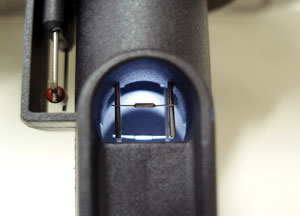
Because the inlet and outlet intake air hoses are often the same size, many MAF sensors can actually be installed backward. Notice in the photo below that the arrow on this MAF sensor housing points toward the engine. Next, MAF sensors, while they might look identical to an amateur mechanic, are very application-specific. Just because the MAF fits does not indicate that it’s calibrated to the engine application.
Last, it’s important to correctly diagnose a failed MAF sensor. For example, the fuel pressure must be tested and remain correct through all ranges of engine operation. In addition, the oxygen sensors must be functioning correctly to provide an accurate air/fuel ratio feedback to the PCM. Assuming the fuel pump and oxygen sensors are functioning correctly, the professional technician will generally use fuel trim numbers to determine if the MAF sensor is accurately measuring the air flowing into the engine.
If the fuel trim numbers exceed 10 percent positive at higher engine speeds, the MAF sensor could be at fault. Whatever the case, most MAF sensor diagnosis requires professional expertise and equipment. But, by understanding the basics of MAF operation, it’s possible for you to offer the amateur mechanic some helpful advice and, if needed, to guide him or her toward professional help in solving his lean air/fuel mixture ratio complaint.
Gary Goms is a former educator and shop owner who remains active in the aftermarket service industry. Gary is an ASE-certified Master Automobile Technician (CMAT) and has earned the L1 advanced engine performance certification. He is also a graduate of Colorado State University and belongs to the Automotive Service Association (ASA) and the Society of Automotive Engineers (SAE).