There’s no doubt that parts professionals will begin selling more variable valve timing (VVT) components as the new generation of vehicles begins coming into aftermarket shops for valve timing repairs. The current versions of VVT were popularly introduced into domestic production about 10 years ago. Just recently, for example, I was called to diagnose a VVT problem on a Ford F150 pickup equipped with the 5.4-liter VVT single overhead camshaft (SOHC) engine and with 245,000 miles on the odometer. In the following text, I’ll use this typical example to illustrate the many issues facing parts professionals on vehicles equipped with variable valve timing.
 Operating Principles
The theory behind variable valve timing is simple. Imagine a column of air speeding through a two-inch pipe at 250 feet per second. Suddenly, the air flow is blocked off by a valve at the end of the pipe. The kinetic energy of the air keeps it moving until a compression wave begins to develop at the valve. The optimum time to open the valve and achieve the greatest air flow is when this compression wave reaches its peak. In contrast, the best time to open the exhaust valve is when a vacuum wave develops at the valve.
Variable valve timing takes advantage of these pressure and vacuum waves to achieve a greater air flow through a given size of engine. Advancing valve timing increases low-speed engine torque while retarding valve timing increases high-speed torque. The Powertrain Control Module (PCM) determines the valve timing position through data supplied by the camshaft position sensors or by valve timing sensors. Be aware of this terminology because some vehicles can use both types of sensors on a single engine.
Parts Nomenclature
The part that actually controls the camshaft position (and the valve timing event) is called a “phaser.” VVT Phaser design includes piston and vane-type configurations. In either case, the phaser uses engine oil pressure to push the piston or rotating vanes against a strong spring. With the vane-type phaser, a clock spring returns valve timing to a “default” position during engine start-up or if the VVT system fails. Another part, called a valve timing solenoid, meters engine oil pressure into the phaser. The VVT solenoid is supplied key-on voltage and the PCM momentarily grounds the circuit to meter oil pressure into the phaser until the valve timing reaches the desired value. The valve timing solenoid also includes a very fine-mesh screen to prevent sludge and debris from entering the mechanism.
Timing Chain Hardware
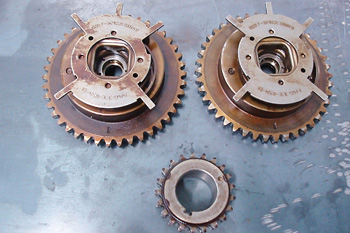
In the case study mentioned above, the timing chain guides and tensioners failed due to extended mileage. As a result, the driver’s side camshaft went out of time, which stored a P0022 diagnostic trouble code and illuminated the “Check Engine” warning light. The mechanic replaced both timing chains, the guides and the camshaft/crankshaft sprockets.
Lubrication Issues
Since correct lubrication is critical to the operation of the VVT phasers and solenoids, it’s doubly important that the correct viscosity of oil is used in a VVT engine. Because VVT designs use a metered oil orifice to adjust valve timing, an oil with a higher than specified viscosity can cause false VVT trouble codes to be stored in the PCM. In addition, the oil must have the correct additive package to keep the engine’s oil passages, phasers, and VVT solenoid screens clean. The complicating factor in the above VVT diagnosis was that, at 245,000 miles, the VVT solenoid screens had accumulated enough varnish to restrict oil flow. An earlier mechanic corrected that condition by removing the screens on one solenoid. Unfortunately, the screens on the remaining solenoid were partially clogged, which caused the driver’s side camshaft to slowly retard after start-up until the engine began backfiring through the exhaust. The problem was solved by replacing the remaining solenoid.