Gasoline direct injection (GDI) is used on most new vehicles and requires a different approach to diagnosis and service. GDI technology has been an integral part of helping to improve fuel economy while reducing emissions, and can be found on more than half of the U.S. fleet. In fact, the use of GDI engines has grown by over 600% since 2010. While GDI systems have been largely useful, these systems encounter specific failures and require an understanding of how they work and how to test them when they set a code.
GDI Spotlight
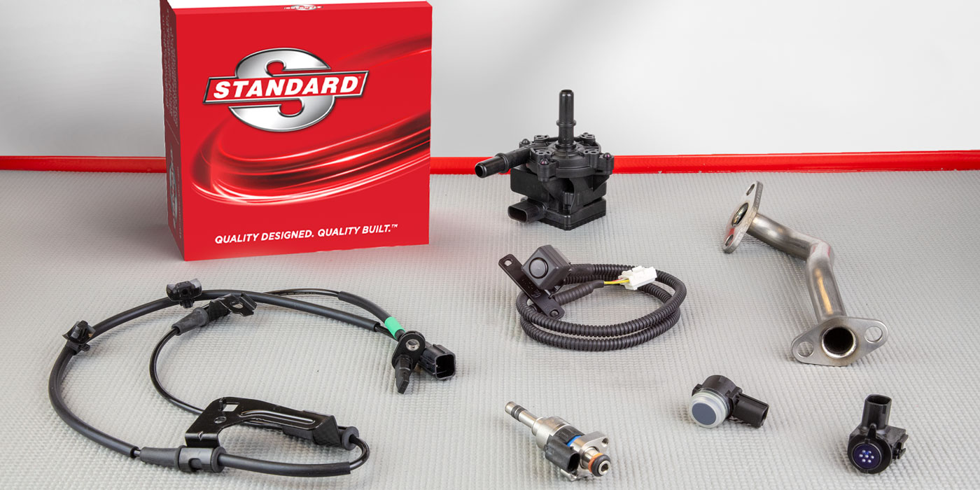
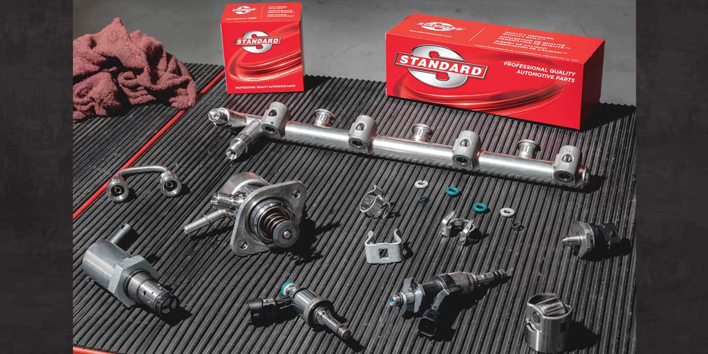
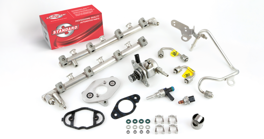
The aftermarket-leading Standard® GDI Program is anchored by Injectors, and also includes High-Pressure Fuel Pumps, Fuel Injector Rail Kits, Fuel Pressure Sensors, Fuel Feed Lines, Fuel Pressure Regulators, and Fuel Pressure Sensor Connectors for a complete line of GDI components.
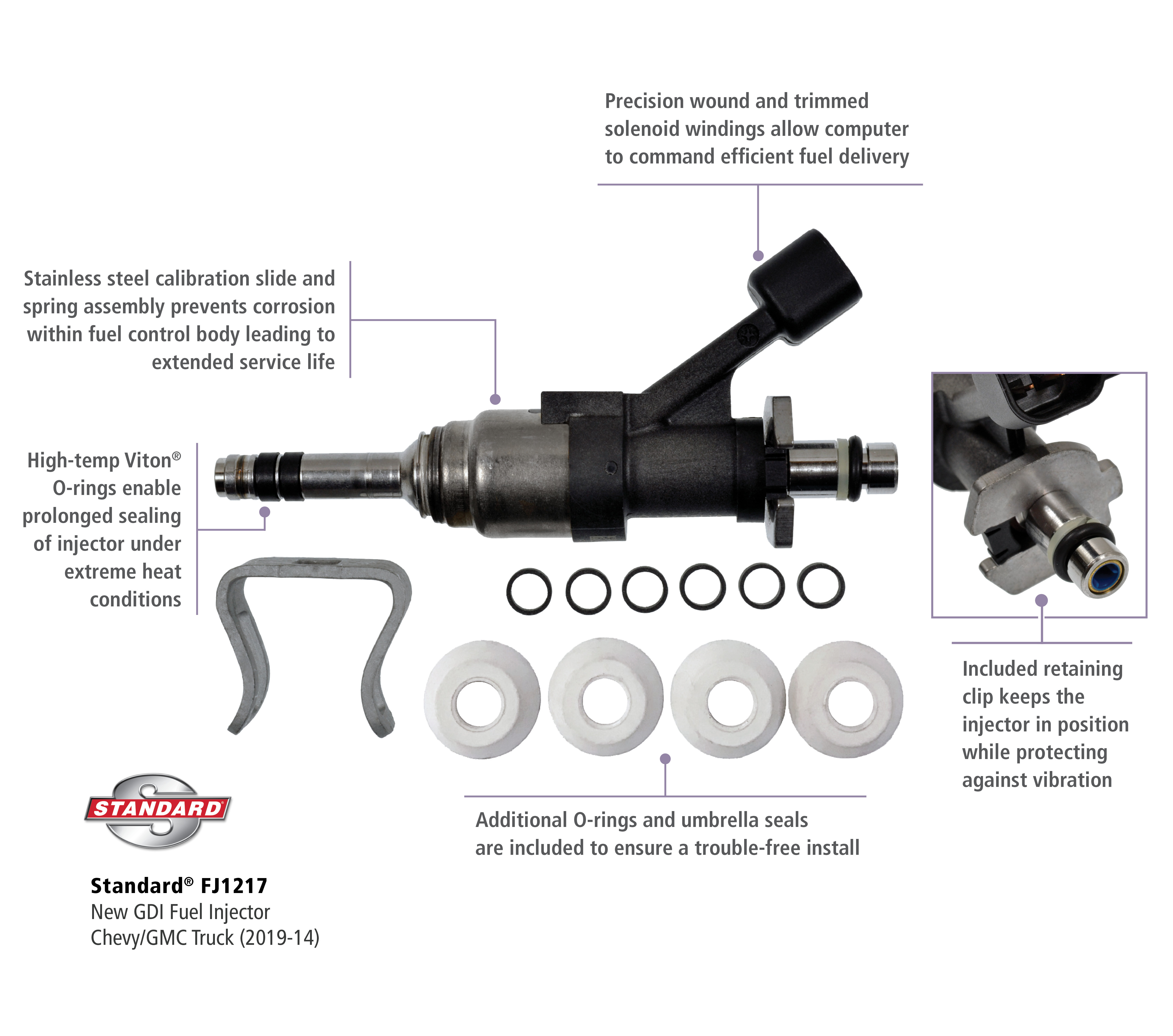
Standard® GDI Injectors are always new, not remanufactured.
Standard’s GDI line-up includes hundreds of part numbers for domestic and import vehicles, including applications through 2022, providing industry-leading late-model coverage. To learn more, visit www.StandardGDI.com.
Why GDI?
In order to meet tighter emission and CAFE (corporate average fuel economy) standards, manufacturers began introducing GDI engines around 2006. The fuel injectors on a GDI engine inject fuel directly into the combustion chamber. Injection takes place primarily on the intake stroke and, in some cases, on the compression stroke as well. As engine speed increases, the amount of time available to inject fuel decreases. In order to increase fuel delivery in a shorter amount of time to produce more power, the fuel pressure is increased. The fuel rail pressure on a GDI engine typically ranges from 300 PSI at idle to 2200 PSI at full load.
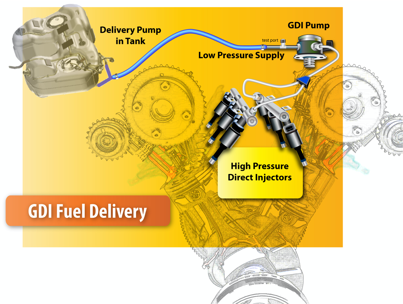
Above is a typical GDI fuel system layout. A low-pressure fuel pump is located in the fuel tank. The low-pressure pump supplies a cam-driven mechanical high-pressure pump with 50-80 PSI of fuel. The mechanical pump then generates the high pressures needed and delivers the high-pressure fuel to the fuel rail. The amount of pressure generated in the fuel rail is determined by an ECM-controlled fuel volume solenoid that is typically part of the mechanical pump.
Diagnosis
There are times when a technician will have to perform a GDI diagnostic test drive to evaluate the GDI system and identify faults. This can help with identifying intermittent faults or system performance that is not yet serious enough for the ECM to set a diagnostic code. The scan tool should be setup to record, at the minimum, the following PIDs:
- Engine RPM
- Throttle angle
- Desired fuel rail pressure
- Actual fuel rail pressure
- GDI pump volume command
Tech Tip: There may be times when the actual fuel rail pressure PID is not available on the OE side of the scan tool. If this is the case, or if the technician’s scan tool cannot display OE scan data, the generic side of the scan tool can be used. The SAE J1979 standard is by used by manufacturers to determine required PIDs for generic OBD. The J1979 standard includes the fuel rail pressure PID for GDI engines.
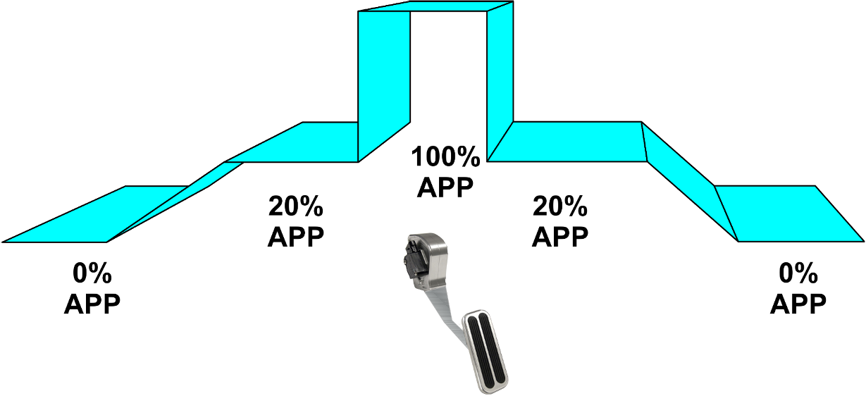
In order to collect the necessary data for analysis, the vehicle should be driven at various engine loads. The scan tool should be set up to record the engine data PIDs selected earlier prior to the test drive. After allowing the engine to idle, the technician should accelerate and hold the APP at about 20%. Then, command a wide-open throttle period, return to a 20% APP command, and finally come to a stop and let the engine idle.
With the data collected, it will need to be reviewed to specifically examine the desired versus actual fuel rail pressure. Was the fuel system able to deliver the desired fuel pressure? If not, the fuel pump regulator command needs to be examined. Was the ECM trying to increase the amount of fuel delivered to the high-pressure pump?
Servicing GDI
Tech Tip: Even with the engine OFF, the pressure in the fuel rail can be very high. Attempting to remove high pressure fuel lines at this time can be dangerous.
Prior to servicing components on a GDI fuel system, it is crucial that there is no pressure retained in the fuel system. Some vehicles can be depressurized using a scan tool command to the ECM, while others will require the removal of the low-pressure pump fuse or relay. The vehicle should then be started and idled until it runs out of fuel and dies.
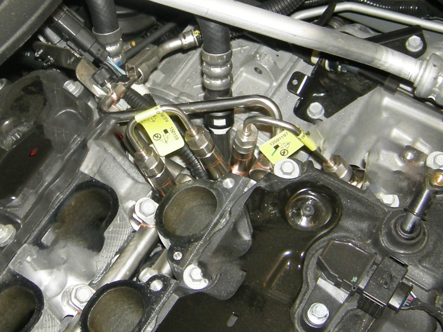
Before disassembling a GDI fuel system for service, it is very important to read service information. Most high-pressure fuel lines are a one-time-use component. When they are torqued down, they will distort to fit, ensuring a tight seal. In the above example, you’ll see a GM 3.6L V6 with the intake manifold removed. Note the yellow tags on the high-pressure lines indicating that they must not be reused. Other manufacturers may not use labels, instead recommending within the service information to discard these lines after removal. Reusing these lines can result in a high-pressure fuel leak which could cause a catastrophic fire.
It will also be necessary to identify all of the tools necessary to complete the task of replacing the fuel injectors. Service information should be read carefully for this information. Once components such as the intake manifold have been removed in order to access the fuel rail, it is important to note that there are two basic types of injector-to-fuel-rail connections. On some applications, the fuel injectors are clipped onto the fuel rail. When removing the fuel rail on these applications, the fuel rail and all of the fuel injectors will come off the engine in one piece.
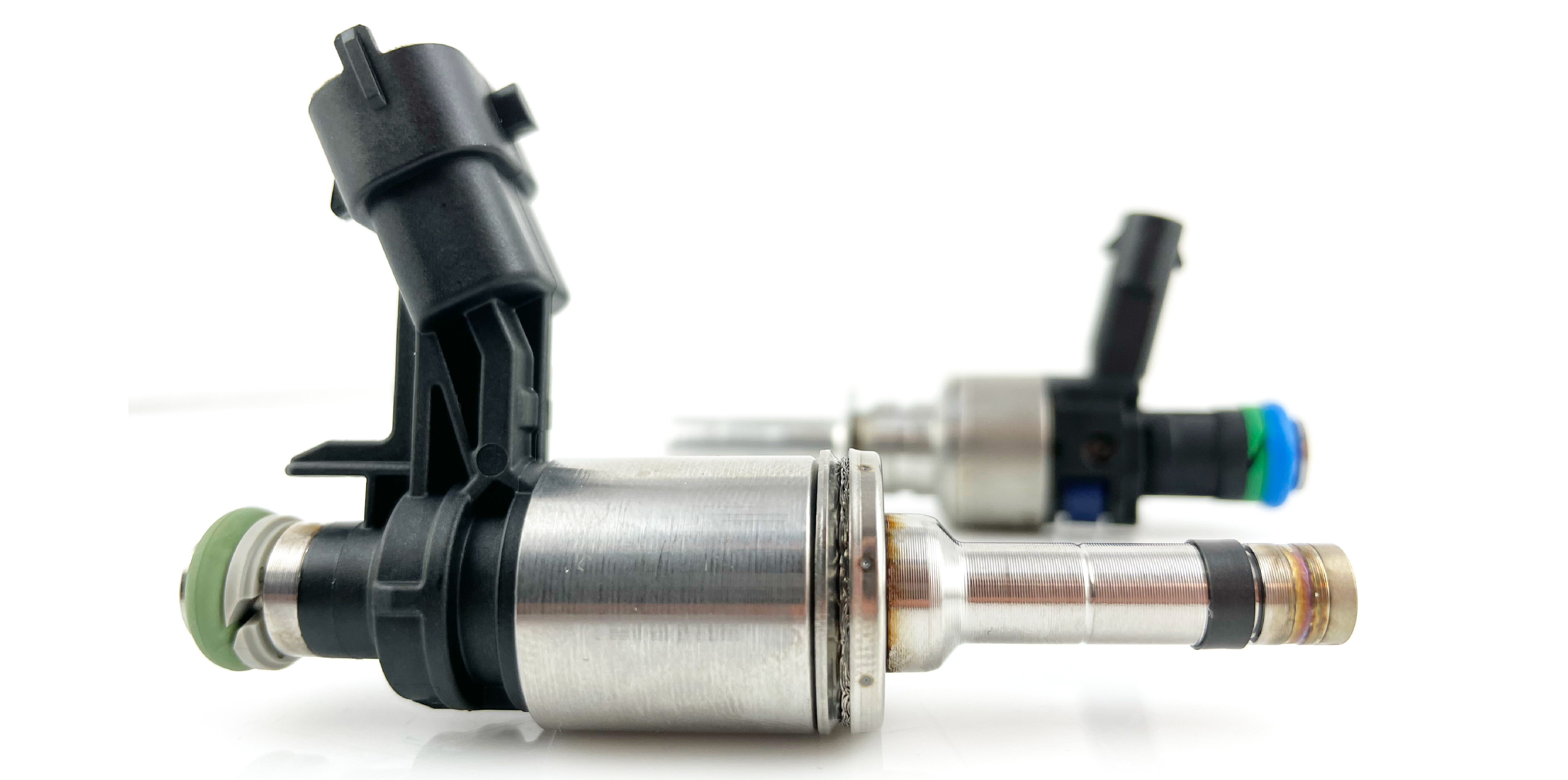
Standard® GDI Injectors are always new, never remanufactured. They are precision engineered and rigorously tested to ensure optimal performance.
On applications that do not use a retaining clip, when you remove the fuel rail you may find that some of the fuel injectors have remained in the cylinder head while the rest come out still attached to the fuel rail. With the fuel injectors removed, be sure to clean the ports in the cylinder head with a correctly sized wire brush and replace the seals on any fuel injectors that are to be reused. Be sure to finish the installation by using the appropriate torque specification and tightening procedure.
For tips on replacing GDI components, search “GDI” on the Standard Brand YouTube channel.